Home
/ 555 Timer Schematic Symbol : 555 Timer Ic Testing Circuit And Its Working - Its function is to discharge the timing capacitor in astable and monostable circuits.
555 Timer Schematic Symbol : 555 Timer Ic Testing Circuit And Its Working - Its function is to discharge the timing capacitor in astable and monostable circuits.
555 Timer Schematic Symbol : 555 Timer Ic Testing Circuit And Its Working - Its function is to discharge the timing capacitor in astable and monostable circuits.. And now a full schematic of the 555 timer oscillator with single step and free run option. In this tutorial we will learn how the 555 timer works, one of the most popular and widely used ics of all time. From wikipedia, the free encyclopedia. In a schematic, the 555 symbol will look similar to this The schematic shows (3) circuits, because one circuit does not work well over the entire vcc range.
The diagram below the 555 die photo and schematic below are interactive. In the schematic above, notice that the threshold pin and. From wikipedia, the free encyclopedia. It's a simple source of oscillating current that can power blinking leds, generate tones, and lots of other useful applications. (1) for all available packages, see the orderable addendum at the end of the datasheet.
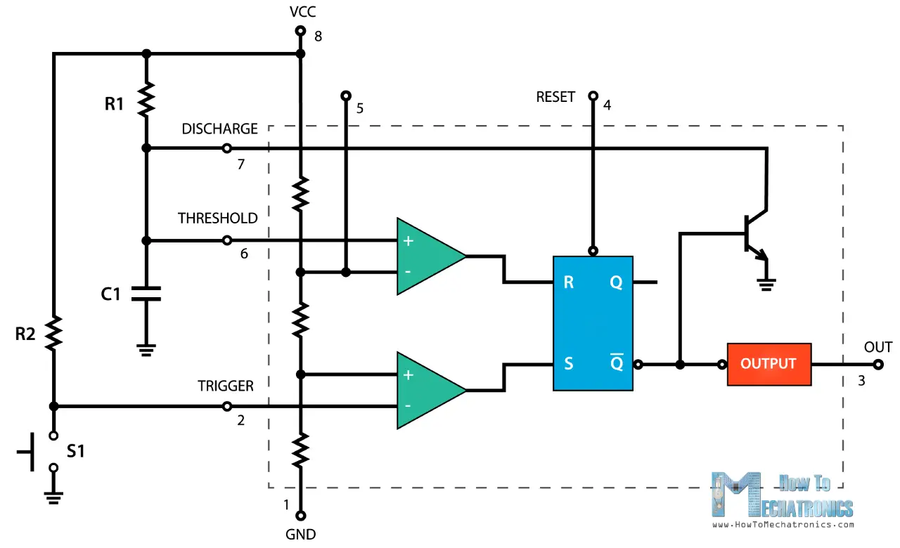
555 Timer Ic Working Principle Block Diagram Circuit Schematics from howtomechatronics.com This circuit generates a stable train of pulses. Its function is to discharge the timing capacitor in astable and monostable circuits. The 555 timer is a simple integrated circuit that can be used to make many different electronic circuits. The 556 shares the power pins. The diagram below the 555 die photo and schematic below are interactive. The versatile 555 timer ic can be used in a variety of circuits like time delays, oscillation, pulse generation, pulse width modulation etc. 555 ic automatically switches back to stable state after some time, this time, for which the 555 stays in quasi stable state, is determined by the time constant of rc network in the circuit. Now the schematic symbol and pcb symbol are created for the 555 timer.
The output of uc (upper comparator) which is reset input to rs.
But when i complied, i got this. From wikipedia, the free encyclopedia. It does so thanks to feedback—the timing capacitor is connected to the trigger. The diagram below the 555 die photo and schematic below are interactive. Transistor q3 is actually connected as a diode with the collector not carrying current. • in the time delay mode, the delay is controlled by • to understand how the capacitor is used in the 555 timer oscillator circuit, you must understand the basic charge and discharge cycles of the capacitor. Usually used to create time delays. The 555 timer ic is an integrated circuit (chip) used in a variety of timer, pulse generation, and oscillator applications. (1) for all available packages, see the orderable addendum at the end of the datasheet. How do i draw this schematic on latex? In a schematic, the 555 symbol will look similar to this Timer b in this method acts as a voltage comparator and has no timing function. The 555 timer, designed by hans camenzind in 1971.
Above schematic diagram shows the 555 timer monostable multivibrator circuit. Monostable mode is great for creating time. The 555 timer ic is an integrated circuit (chip) used in a variety of timer, delay, pulse generation, and oscillator applications. With this information you will learn how how the 555 works and will have the experience to build some of the circuits below. The 555 timer is capable of producing accurate timing ranges from microseconds to hours and therefore has many practical uses for every level of electronics.
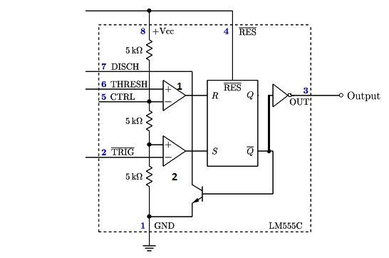
555 Timer Ic Introduction Basics Working With Different Operating Modes from www.engineersgarage.com In the schematic above, notice that the threshold pin and. You can watch the following video or read the written tutorial below. So far i have tried drawing from this link which was supposed to produce. Although a circuit common symbol is shown, the collector is not. This tutorial provides sample circuits to set up a 555 timer in monostable, astable, and bistable modes as well as an in depth by wiring the 555 timer with resistors and capacitors in various ways, you can get it to operate in three different modes: This article covers every basic aspect of 555 timer ic. For standard 555 timers use timing resistor values between 1k ohms and 1m. The 555 timer is a simple integrated circuit that can be used to make many different electronic circuits.
Transistor q3 is actually connected as a diode with the collector not carrying current.
The schematic of the pulse position modulator using two 555 timer ic's is shown below. In a schematic, the 555 symbol will look similar to this The 555 timer was introduced over 40 years ago. In the mwe, two tikz objects are created that can be placed and identified as the components in schematic editors such as proteus or eagle, pins will be identified. It does so thanks to feedback—the timing capacitor is connected to the trigger. Derivatives provide two (556) or four (558) timing circuits in one package. The 555 timer ic is an integrated circuit (chip) used in a variety of timer, delay, pulse generation, and oscillator applications. Outputs an oscillating pulse signal. When the 555 output (pin 3) is low the discharge pin is connected to 0v internally. Due to its relative simplicity, ease of use and low cost it has been used in literally thousands of applications. 555 ic automatically switches back to stable state after some time, this time, for which the 555 stays in quasi stable state, is determined by the time constant of rc network in the circuit. There are several different part numbers that are 555 timers, and most of them are similar enough to ignore the differences, but check the data sheet for the particular limitations. Transistor q3 is actually connected as a diode with the collector not carrying current.
And now a full schematic of the 555 timer oscillator with single step and free run option. The 555 timer is a simple integrated circuit that can be used to make many different electronic circuits. The schematic of the pulse position modulator using two 555 timer ic's is shown below. Although a circuit common symbol is shown, the collector is not. Learn about the 555 timer and how it works in astable mode.
555 Timer Pinout Basic Electronic Circuits Voltage Controlled Oscillator Timer from i.pinimg.com The 555 timer is a simple integrated circuit that can be used to make many different electronic circuits. It is a slave to timer a. • in the time delay mode, the delay is controlled by • to understand how the capacitor is used in the 555 timer oscillator circuit, you must understand the basic charge and discharge cycles of the capacitor. When the 555 output (pin 3) is low the discharge pin is connected to 0v internally. Due to its relative simplicity, ease of use and low cost it has been used in literally thousands of applications. 555 ic automatically switches back to stable state after some time, this time, for which the 555 stays in quasi stable state, is determined by the time constant of rc network in the circuit. With this information you will learn how how the 555 works and will have the experience to build some of the circuits below. The 555 timer changes its output depending on the state of two inputs.
The 555 timer ic is an integral part of electronics projects.
The 555 timer is one of the most widely used integrated circuits in electronics projects 555 timer schematic. The 555 timer is a simple integrated circuit that can be used to make many different electronic circuits.
